

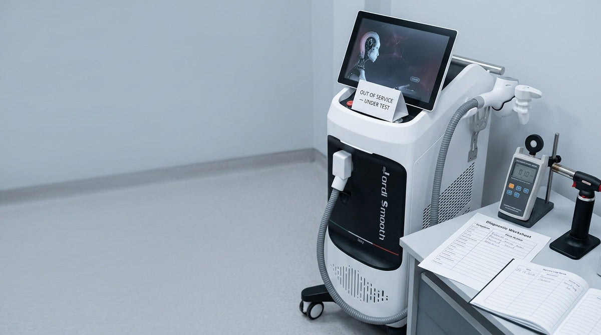
Why a Diode Laser Machine Loses Power: 9 Causes and a Diagnostic Checklist
When a diode laser machine loses power, the fault is not always the laser bar. Optics, cooling, cables, calibration, settings and measurement method each affect what the operator experiences as "weak treatment." Run the diagnostic sequence from operator-accessible checks through instrumented output testing before escalating — never raise settings to compensate for unexplained power loss.
Quick answer: How should a technician diagnose diode-laser power loss?
Match the symptom to a first check and action. Weak from startup usually points to settings, optics, calibration or supply — verify at operator level. Starts strong and then fades points to cooling, coolant flow or thermal derating — pause treatment and complete the approved thermal inspection. Power that changes when the cable moves points to the handpiece cable or connector — pause and quarantine. Any burning smell, smoke, coolant leak or repeated thermal shutdown that returns after cooling is a stop-use signal — remove the machine from service and escalate.
How to use this guide
The checks below are diagnostic tools for trained technicians and equipment owners, not a substitute for the manufacturer's IFU, service manual or authorized field service. All example values in the evidence package are illustrative — replace each field with the affected machine's actual readings, instrument identity and calibration date. Review the current LEFIS diode laser collection only to shortlist platforms; obtain warranty, spare-parts and remote-diagnostic terms in writing for the exact model.
Diode Laser Power-Loss Diagnostic Decision Table
For technicians who need direction before reading further, the table below matches the observed symptom to the first check category and the correct action. The action column reflects severity, not counting — one Critical symptom (Stop use) is enough to remove the machine from service; two Verify items are not.
QUICK DIAGNOSTIC — MATCH SYMPTOM TO FIRST CHECK AND ACTION
|
SYMPTOM |
FIRST CATEGORY TO CHECK |
ACTION |
|
Weak from startup |
Settings, optics, calibration, supply |
Verify |
|
Starts strong, then fades |
Cooling, water flow, temperature |
Pause |
|
One handpiece is weak |
Handpiece, cable, optical path |
Verify |
|
All handpieces are weak |
Supply, cooling, calibration, main system |
Escalate |
|
Power changes when cable moves |
Cable or connector |
Pause |
|
Display looks normal, treatment feels weak |
Measurement, optics, laser-bar output |
Verify |
|
Frequent thermal warnings |
Water flow, pump, fan, coolant |
Escalate |
|
Burning smell, smoke, or coolant leak |
Immediate isolation |
Stop use |
Illustrative decision table. Actions define severity: Verify = operator-level check under controlled conditions; Pause = stop treatment and complete the approved inspection before resuming; Escalate = send the full evidence package to technical support; Stop use = remove from service and contact the manufacturer. Individual Critical findings override any count-based rule.
Is the Machine Really Losing Laser Power?
"Weak treatment" is not proof of laser-bar failure. Separate the two categories before starting hardware diagnosis.
True optical power loss = measured output on a calibrated instrument declines against baseline at the same settings, and the decline persists across repeat tests or worsens as the system warms.
Apparent power loss = the operator experience of weakness with no change to the laser bar. Common contributors: dirty window, altered fluence setting, different spot size or pulse duration, poor contact, changed technique, or measurement inconsistency.
|
TRUE POWER LOSS |
APPARENT POWER LOSS |
|
Measured optical output declines |
Output may remain normal |
|
Persists across controlled repeat tests |
Depends on settings or technique |
|
Requires instrumented diagnosis |
Usually found through workflow checks |
|
Points to laser bar or supply |
Points to optics, settings or measurement |
Confirm the category before assuming a hardware fault. A confirmed measured reduction that persists after operator-level checks typically indicates a laser-source or driver issue; anything else should be checked against the workflow and settings first.
9 Reasons a Diode Laser Machine Loses Power
Each cause below follows the same structure: what the operator observes, the most likely diagnostic domain, and the safe first action. Sub-labels are kept inline to keep the table of contents readable rather than filling it with repeated four-level sub-headings.
1. Laser-Bar Degradation
Symptom: gradual, session-over-session decline in measured output at the same settings; no full recovery after cooling. Often correlates with high accumulated shot count.
Likely cause: cumulative operating hours, thermal or current stress causing diode-emitter aging. Partial emitter failure produces an uneven beam profile before total loss.
First action: compare measured output against baseline. Review shot counter, cooling history and error log. Escalate to service — laser-bar assessment is not an operator task.
|
NORMAL AGING |
PREMATURE DEGRADATION |
|
Gradual, over long service |
Sudden or accelerated |
|
Correlates with high shot count |
May occur relatively early |
|
Stable cooling and driver history |
Often follows thermal or electrical fault |
|
Similar decline across emitters |
Can affect specific emitters |
Normal aging is gradual; sudden decline after a thermal or electrical fault is not. See the diode laser lifespan and ROI guide for how manufacturer-published shot ratings relate to expected bar life.
2. Dirty or Damaged Optical Window

Symptom: abrupt drop in treatment effect without a settings change. Visible residue, cloudiness or scratches on the treatment window.
Likely cause: gel residue, dust, fingerprints, dried cleaning solution or coating damage. Contamination inside the sealed optical path requires service.
First action: follow the manufacturer's approved cleaning procedure. Quarantine any handpiece with visible sapphire damage.
|
DIRTY OPTICAL PATH |
WORN LASER BAR |
|
Often abrupt apparent loss |
Usually progressive |
|
May be externally visible |
Rarely visible externally |
|
Reduces transmitted beam |
Reduces generated output |
|
Cleaning may restore performance |
Requires measured diagnosis or service |
3. Poor Water Flow
Symptom: output starts near normal, then declines during a session. Handpiece feels warmer than usual. Low-flow warning or intermittent thermal error.
Likely cause: low coolant, weak pump, air bubbles, blocked filter, kinked tubing or deposits. A worn low-flow sensor can trigger the warning without a real flow problem.
First action: check coolant level and any visible flow indicator. Inspect tubing for kinks. Do not open a sealed cooling loop.
|
NORMAL COOLING LOOP |
RESTRICTED COOLING LOOP |
|
Stable coolant movement |
Weak or intermittent flow |
|
Stable handpiece temperature |
Temperature climbs |
|
No low-flow error |
Flow warning may appear |
|
Stable output over session |
Output falls as heat rises |
4. High Operating Temperature

Symptom: power declines only after the machine warms. The cold-start test appears normal. Repeated thermal derating during high-frequency use.
Likely cause: blocked vents, failed fan, insufficient coolant flow, warm room, sustained high-duty-cycle operation or a degraded thermal interface.
First action: clear vents and confirm the ambient is within spec. Repeat the same measured test cold and warm — a meaningful gap points to a thermal cause.
|
COLD-START READING |
WARM-SYSTEM READING |
|
Tests initial output only |
Tests thermal stability under load |
|
May appear normal |
Reveals heat-related decline |
|
Low accumulated heat |
Represents sustained treatment |
|
Insufficient alone |
Stronger diagnostic evidence |
5. Power Supply or Laser Driver Problem
Symptom: weakness across every handpiece, unstable output or shifts with mains-supply variation. Often accompanied by protective derating in software.
Likely cause: unstable mains, driver current limitation, voltage drop under load, ripple, aging capacitors or connector resistance in the internal DC path.
First action: record settings and behaviour, then escalate. Internal voltage probing, current-limit adjustment and driver-board work are not operator tasks and are excluded here for safety reasons.
|
OPTICAL-SOURCE ISSUE |
ELECTRICAL DELIVERY ISSUE |
|
Laser bar cannot produce expected output |
Bar may be healthy |
|
Correct supply still yields low output |
Supply values may be unstable |
|
Often requires output testing |
Requires electrical diagnostics |
|
Handpiece-level fault |
System-wide fault |
6. Calibration Drift
Symptom: commanded (display) energy no longer matches measured output on a calibrated instrument. Recently serviced or updated systems are more likely candidates.
Likely cause: recent handpiece replacement, software update, sensor drift or component aging. The display value is a software command, not a physical measurement of the beam.
First action: compare display against a measured test. Do not reset stored calibration without manufacturer instruction. Calibration interval should follow the exact machine manual.
|
DISPLAY VALUE |
MEASURED OUTPUT |
|
Software command |
Physical measurement |
|
May remain unchanged |
Reveals true drift |
|
Useful operationally |
Needed for diagnosis |
|
Not proof of optical output |
Requires calibrated equipment |
7. Handpiece Cable or Connector Fault

Symptom: power drops when the cable is moved. Handpiece disconnects intermittently. The connector runs warm. One handpiece is affected while another performs normally.
Likely cause: crushed cable, tight bends, strain damage near the handpiece, bent connector pins or intermittent contact. Damage often develops at the strain relief before it is visible along the cable.
First action: visual inspection only. Do not repeatedly reconnect a live connector to reproduce the fault. If moving the cable changes performance, quarantine the handpiece and request repair.
|
CONSTANT LOW OUTPUT |
INTERMITTENT LOW OUTPUT |
|
More likely systematic |
More likely connection-related |
|
Same reading in each position |
Changes with cable movement |
|
Check optics, calibration and output |
Check cable and connector first |
|
Reproducible on the bench |
Difficult to reproduce |
Escalate handpiece and cable faults through diode laser technical support with the affected handpiece serial number and cable inspection photographs.
8. Incorrect Settings or Changed Treatment Mode
Symptom: machine capability is unchanged, but the selected protocol has lower fluence, different pulse width, changed spot size, altered frequency or a different mode (stamping vs SHR/glide).
Likely cause: saved preset overwritten, operator profile changed, software reset or wrong wavelength selected on multi-wavelength platforms.
First action: restore the approved protocol and repeat the same measured test. Review any preset change with the clinical lead.
|
MACHINE CAPABILITY |
SELECTED TREATMENT OUTPUT |
|
Maximum available system output |
What the current protocol requests |
|
Hardware characteristic |
Software or operator setting |
|
Rarely changes session to session |
Can change every session |
|
Verified through instrumented test |
Verified against approved protocol |
9. Incorrect Measurement Method
Symptom: "it feels weaker." No calibrated measurement supports the claim, or comparison tests used different settings or handpieces.
Likely cause: client sensation, thermal feel and visible light are not diagnostic. Repeat tests must control spot size, pulse width, frequency, wavelength, handpiece, warm-up state, cooling state and sensor position.
First action: document exact conditions and repeat at the same settings. An instrumented reading is the diagnostic reference — subjective observation is only a signal to test.
|
SUBJECTIVE OBSERVATION |
INSTRUMENTED MEASUREMENT |
|
Fast |
Repeatable |
|
Useful to detect change |
Useful to confirm cause |
|
Influenced by cooling and patient sensation |
Quantifies output |
|
Cannot isolate laser-bar health |
Supports service diagnosis |
Read the Pattern Before Reading the Symptom
Three pattern checks separate most causes before an instrument is used.
Sudden vs gradual
|
SUDDEN — MINUTES, HOURS OR DAYS |
GRADUAL — WEEKS OR MONTHS |
|
Connection or fault more likely |
Wear or degradation more likely |
|
Check recent changes first |
Check trend logs first |
|
May be intermittent |
Often repeatable |
|
Cable, optics, settings, cooling |
Bar aging, contamination, pump wear, drift |
Cold-start vs warm-system
Weak immediately typically points to settings, optical window, handpiece recognition, cable, calibration, supply or the laser bar itself. Starts strong then weakens typically points to cooling, coolant flow, fan operation or thermal derating.
One handpiece vs whole machine
|
ONE HANDPIECE AFFECTED |
EVERY HANDPIECE AFFECTED |
|
Localize the diagnosis |
Look upstream |
|
Cable, optics or module |
Supply, cooling or control |
|
Compare with a known-good approved unit |
Compare system-wide readings |
|
Handpiece calibration may be affected |
Main-unit calibration or supply may be affected |
Diagnostic Checklist: From Lowest-Risk Checks to Technical Service
Work top to bottom. Do not skip earlier steps because a later step feels more definitive — most weak-treatment reports resolve above the instrumented-testing line.
STEP-BY-STEP DIAGNOSTIC WORKFLOW
|
STEP |
CHECK |
WHAT TO RECORD |
ACTION |
|
1 |
Record the symptom |
When it began, sudden vs gradual, cold vs warm, which handpiece, error codes, recent service |
Verify |
|
2 |
Confirm the settings |
Fluence, pulse width, frequency, spot, wavelength, mode, operator profile |
Verify |
|
3 |
Inspect the optical window |
Visible residue, cloudiness, scratches; approved cleaning only |
Verify |
|
4 |
Inspect cable and connectors |
Physical condition, strain relief, pin damage — visual only |
Verify |
|
5 |
Check cooling status |
Coolant level, flow indicator, temperature reading, fan noise, warnings |
Pause |
|
6 |
Repeat under controlled conditions |
Same handpiece, settings, spot, pulse width, warm-up state |
Verify |
|
7 |
Review error and service logs |
Codes with timestamps, service dates, software version |
Pause |
|
8 |
Obtain instrumented output test |
Approved sensor, controlled parameters, printed reading |
Escalate |
|
9 |
Escalate with evidence |
Full log package, video, serial numbers, test data |
Escalate |
Illustrative workflow. Adapt the sequence and severity thresholds to the specific machine's IFU and the clinic's service agreement. Actions above do not replace the manufacturer's authorized diagnostic procedure.
Sample Diagnostic Evidence Package

Technical support cannot troubleshoot from "the machine feels weak." The example below shows the field structure a well-formed evidence package contains — copy the labels and fill in values from the affected unit.
EXAMPLE FIELDS — REDACTED FOR ILLUSTRATION
|
FIELD |
EXAMPLE VALUE |
|
Machine model / serial |
K-series diode / SN ████████ |
|
Handpiece serial / total shots |
HP ████████ / ██,███,███ |
|
Software version |
v █.██.██ |
|
Wavelength / spot / pulse / frequency |
808 nm / ██×██ mm / ██ ms / █ Hz |
|
Commanded fluence |
██ J/cm² |
|
Measured optical output |
██ W · instrument █████ · cal date YYYY-MM-DD |
|
Ambient room / coolant start temp |
██ °C / ██ °C |
|
Cold-start / warm-system reading |
██ W / ██ W (after 20 min) |
|
Error codes with timestamps |
E███ at HH:MM:SS · E███ at HH:MM:SS |
|
Recent service or parts replacement |
Description, date, technician |
|
Attached files |
Screen photos, cold/warm test video, error log export |
Values are illustrative and shown only to demonstrate field structure. Real submissions require the actual machine's readings, instrument identity, calibration date and manufacturer-approved test conditions. Do not treat any example figure as a benchmark.
What Not to Do When a Diode Laser Feels Weak
Every action below either masks the fault, creates a safety risk or invalidates warranty and diagnostic evidence.
- Increase fluence to compensate for unexplained power loss
- Bypass thermal warnings or override low-flow alarms
- Raise driver current or attempt supply modification
- Open sealed electrical sections
- Reset calibration without manufacturer instruction
- Use unapproved coolant or generic solvents
- Polish or abrade an optical window
- Repeatedly reconnect a live electrical connector to reproduce a fault
- Continue treating clients while output is unpredictable
When to Stop Using the Machine Immediately
Stop treatment and remove the machine from service if any of the following are present: burning smell, smoke, sparking, coolant leak, cracked optical window, exposed cable conductor, repeated thermal shutdown that returns after cooling, low-flow alarm that cannot be cleared, unexplained energy spikes, unstable output during treatment, uncontrolled firing, safety interlock failure or repeated handpiece disconnection during a session.
|
MONITOR OR DOCUMENT |
REMOVE FROM SERVICE |
|
Cosmetic casing wear |
Electrical damage |
|
Minor variation within tolerance |
Unexplained output instability |
|
Scheduled maintenance approaching |
Safety warning or interlock failure |
|
Non-critical log entry |
Burning smell, smoke or coolant leak |
A single Critical finding overrides any combined count of minor items. Do not average severity. Restarting a machine to "see if the code clears" can erase useful diagnostic evidence.
What Information Technical Support Needs
The full set of fields in the evidence-package table above. Send them together — a single missing field usually triggers another round of questions before diagnosis begins. Include cold-start and warm-system readings taken at the same settings, cooling values at the time of the fault, and any recent maintenance or parts replacement. See the training, warranty and after-sales support page for the escalation channels LEFIS publishes.
Repair vs Replace the Handpiece or Laser Module
|
REPAIR IS USUALLY REASONABLE WHEN |
REPLACEMENT IS USUALLY REASONABLE WHEN |
|
Fault is a cable, connector or sensor |
Laser bar reaches documented end-of-life |
|
Pump, fan or window is serviceable |
Output cannot meet specification after service |
|
Machine is otherwise healthy |
Repeated major component failures |
|
Supported spare available on reasonable lead time |
Repair economics no longer justify remaining machine life |
Economics depend on remaining machine life, warranty status and current spare-part pricing. See the diode laser machine buying guide for how bar life and handpiece cost feed into replacement decisions, and the diode laser manufacturer comparison (published by LEFIS) for service and support context across suppliers. Methodology, scoring weights and commercial relationships should be disclosed on the comparison page — treat the ranking as one input among several.
Preventing Future Power Loss
Preventable power loss reduces to six habits: clean optical surfaces with approved products; check the cooling loop weekly; respond to temperature warnings the first time they appear; protect handpiece cables from tight coils and strain; record shot counts and software or calibration changes as they happen; and trend measured output monthly rather than waiting for a complaint. Trend data turns a service call into a scheduled parts order.
Final Diode Laser Power-Loss Diagnostic Checklist

Before releasing the machine back into service, confirm the technician has:
- recorded the symptom with sudden vs gradual and cold vs warm patterns
- confirmed operator-accessible settings against the approved protocol
- inspected the optical window using the manufacturer-approved procedure
- inspected the handpiece cable and connector visually
- checked coolant level, flow indicator, temperature and fan operation
- repeated the measured test under controlled conditions
- compared results against baseline and against a known-good approved handpiece
- reviewed error and service logs for recurrence
- obtained an instrumented optical-output reading against manufacturer spec
- assembled the full evidence package before escalating
- removed the machine from service if any stop-use criterion is met
- logged the incident and outcome in the service record
Request Remote Diagnostics or Replacement Parts
Weak treatment output does not automatically prove laser-bar failure. Group the nine causes into optics, thermal, electrical, hardware, settings and measurement — and work from operator checks toward instrumented testing. Measured output beats subjective sensation; stop-use criteria always come first.
Compare the LEFIS diode laser collection and use the training, warranty and after-sales support page to request remote diagnostics, service support or replacement parts. Ask for a written response that identifies compatible handpiece part numbers, spare-parts lead time, warranty period, exclusions and the remedy for confirmed reduced output during the coverage period.
Information to include in the diagnostic request
Provide the operating data below so support can match compatible spares and open a diagnostic case for the correct model. Use the response as an input to the clinic's own service record; do not treat a supplier estimate as a substitute for the manufacturer's authorized diagnostic procedure.
|
FIELD |
WHAT TO SEND |
WHY IT'S NEEDED |
|
Machine model / serial |
Exact model and serial number (e.g. K-series diode / SN…) |
Confirms compatible handpiece and driver family |
|
Handpiece serial |
Serial number of the affected handpiece |
Isolates the diagnostic to a specific unit |
|
Software version |
As displayed on the console |
Rules out software-related derating |
|
Shot count and operating hours |
Current counter reading and estimated hours in service |
Anchors bar-life discussion |
|
Measured output |
Reading, sensor identity, calibration date and test parameters |
Objective evidence of true vs apparent loss |
|
Ambient and coolant conditions |
Room temperature and coolant temperature at test |
Rules out thermal-only causes |
|
Cold-start and warm-system readings |
Same settings, taken 20 minutes apart |
Detects thermal derating vs stable reduction |
|
Error codes with timestamps |
Full code, time and screen photo |
Speeds pattern recognition on the support side |
|
Recent service or parts replacement |
Dates, technicians, parts |
Rules out post-service calibration drift |
|
Attached evidence |
Screen photos, cold/warm test video, error-log export |
Reduces the number of clarifying questions |
Submit the request through the training, warranty and after-sales support page and ask for a written response identifying spare-parts availability, lead time, warranty scope and any diagnostic remote-session slot. Compatibility, pricing and remedy terms should be confirmed for the exact model before payment.
FAQs
Why is my diode laser machine losing power?
The most common causes are dirty optics, poor water flow, elevated operating temperature, cable or connector faults, calibration drift, changed settings and — after long service — laser-bar aging. Confirm the pattern first (sudden vs gradual, cold vs warm, one handpiece vs all) before assuming a hardware failure. Most weak-treatment reports resolve above the instrumented-testing line.
How can I tell if a laser diode is bad?
Compare measured optical output against baseline on a calibrated instrument under the same settings. A confirmed reduction that persists after operator-level checks — clean optics, correct settings, adequate cooling, healthy cables — typically indicates a laser-source or driver issue. Diagnosis and replacement are not operator tasks; send the full evidence package to authorized service.
How do you test the power of a diode laser machine?
Use an approved optical-power or energy sensor at the treatment window with defined spot size, pulse width, frequency and warm-up state. Record cold-start and warm-system readings, ambient conditions and instrument calibration date. Display energy is a software command — it is not a substitute for a measured reading and cannot confirm true vs apparent power loss on its own.
Can overheating make a diode laser lose power?
Yes. Thermal derating is a protective response — the driver reduces output when internal temperatures rise. Repeated derating during a session commonly indicates blocked vents, coolant loss, weak pump flow or a warm treatment room, not a failing laser bar. Continuing through repeated warnings risks bar damage and voids many warranties.
How long do diode laser bars normally last?
Bar life depends on operating hours, thermal history, current stress and duty cycle rather than a fixed shot number. Use the manufacturer's published shot rating for the specific model rather than a generic figure. Any specific hour or shot number quoted without the machine model, cooling design and duty-cycle assumption should be treated as illustrative only.
Can a dirty optical window reduce laser power?
Yes, and it is one of the most common causes of an abrupt drop in treatment effect. Gel residue, dust and dried cleaning solution reduce beam transmission. Clean only with manufacturer-approved products; never polish or abrade the window. Damage inside the sealed optical path requires service.
Can poor water flow make a diode laser weaker?
Yes — indirectly. Reduced flow allows temperatures to climb, triggering thermal derating and progressive session-fade. Low coolant level, weak pump, air bubbles, blocked filters and deposits are the usual mechanical causes. Do not open a sealed cooling loop or add generic coolant to compensate.
How do I know whether the handpiece or power supply is faulty?
Substitute a known-good approved handpiece and repeat the same measured test. If the second handpiece performs normally, the fault is localised to the first handpiece or its cable. If both are weak, look upstream to supply, cooling or main-system calibration. Do not swap unapproved or incompatible handpieces to run this test.
Should I increase the settings if a diode laser feels weak?
No. Raising fluence to compensate masks the underlying fault and can expose patients to unsafe energy once the real problem is corrected. Diagnose first, then treat with the approved protocol. "How to increase laser power" is not a valid response to unexplained output loss.
When should a weak diode laser machine be taken out of service?
Immediately for burning smell, smoke, coolant leak, cracked optics, exposed conductors, uncontrolled firing, safety interlock failure or repeated thermal shutdown that returns after cooling. Unstable output during a treatment is also a stop-use signal. A single Critical finding overrides any combined count of minor items.
Sources
- How to Improve Laser Diode Lifetime — Advice and Precautions for Mounting · RPMC Lasers
- 5 Tips for Troubleshooting Laser Diode Hardware · Arroyo Instruments
- Five Sources of CW Laser Diode Failure and How to Prevent Them · Leonardo Electronics
- Laser Products and Instruments · U.S. Food & Drug Administration
- Performance Standards for Light-Emitting Products (21 CFR 1040.10) · U.S. Food & Drug Administration
- IEC 60825-1 — Safety of Laser Products · International Electrotechnical Commission
- ISO 13485 — Medical Devices Quality Management Systems · International Organization for Standardization


Looking for something else?

Do Men Get Cellulite? Causes Differences & What to Know
LEARN MORE
Does Radio Frequency Skin Tightening Work? Results & How It Works
LEARN MORE
Do You Shave Before Laser Hair Removal? Prep Tips & Why It Matters
LEARN MORE
How to Get Rid of Age Spots: Treatments. Natural Remedies & Prevention
LEARN MORELooking for something else?
How to Heal Ingrown Hair: Causes. Treatments & Healing Time
LEARN MORE
How to Get Rid of Freckles: Effective Treatments & Natural Tips
LEARN MORE
Top 10 Picosecond Laser Machine Manufacturers for Clinics in 2026
LEARN MOREYou may also like


Further reading

Tattoo Removal Laser Machine Cost and Ownership Guide

CO2 Laser Treatment Room Setup Checklist

Aesthetic Machine Factory Acceptance Test Before Shipment


